
The Erasmus+ project is not only about the technical project goal, but also about an international exchange and personal development of the participants. It is worked with different educational institutions across countries, whereby partnerships are created and established. The students get the opportunity to travel to lesser-known countries and cities. They gain insight into the culture of the country and establish friendships throughout Europe. Great emphasis is placed on strengthening Art.2 of the EU Treaty, which addresses the issue of pluralism and tolerance. Digitalization in vocational education can also counteract problems such as social distancing through VR and media.
Vocational School Horb a.N. – Germany
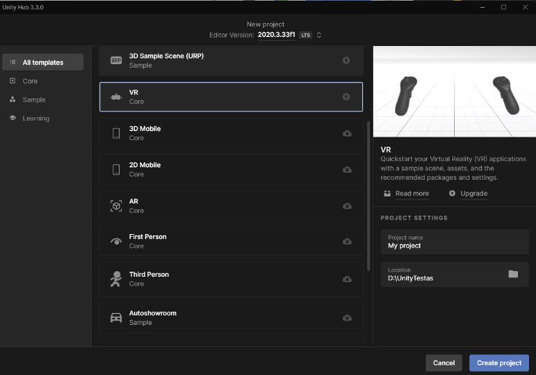
Manual to open a VR core Scene in Unity and to combine it with HP Reverb G2
Step-by-step manual to transfer CAD Models from SolidWorks to Unity
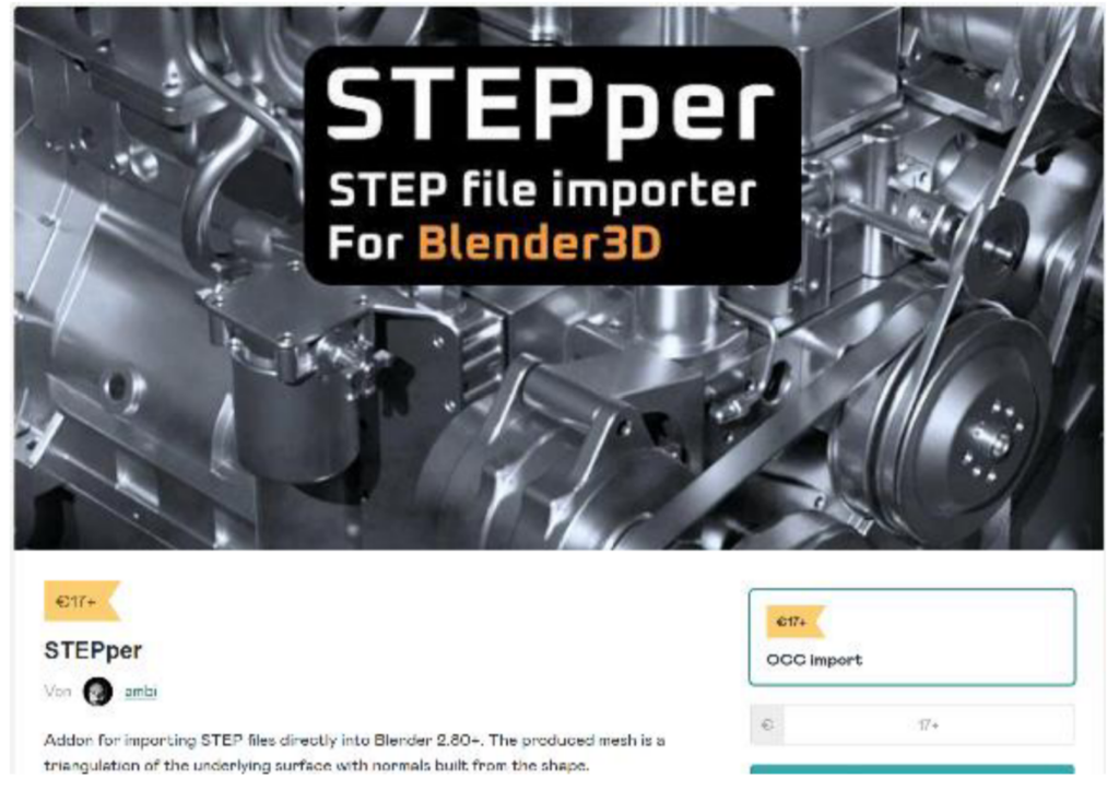
To transfer the CAD model from SolidWorks to Unity, it is important to save the CAD model in assemblies so that the individual parts are compact in one file. Then you must buy a program for example “Stepper”, which costs 17€.
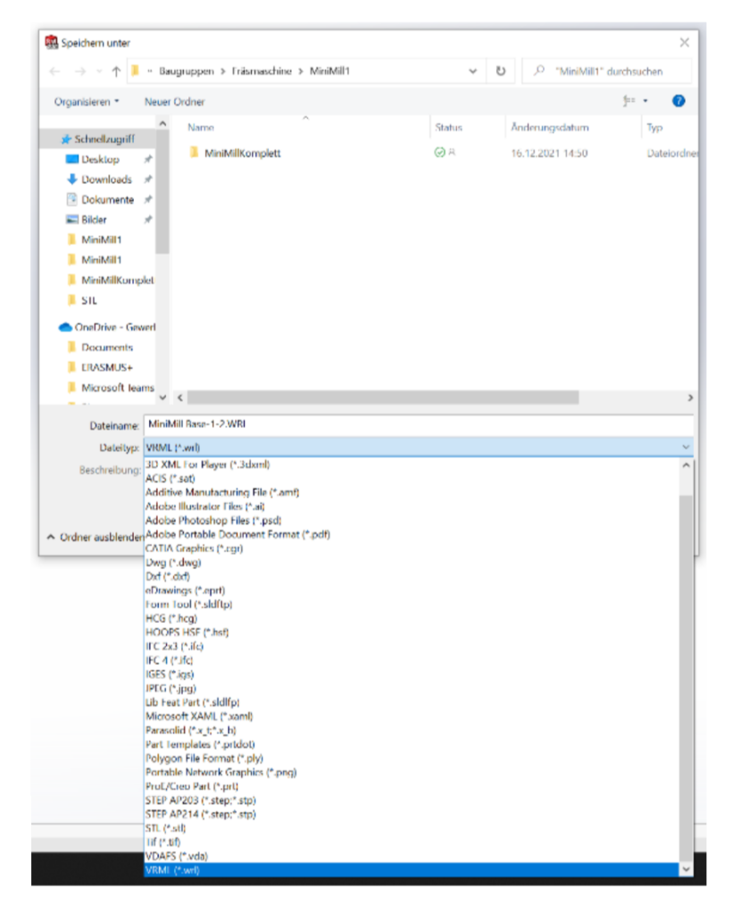
With this program you can save the assemblies as an VRML (wrl.) file.
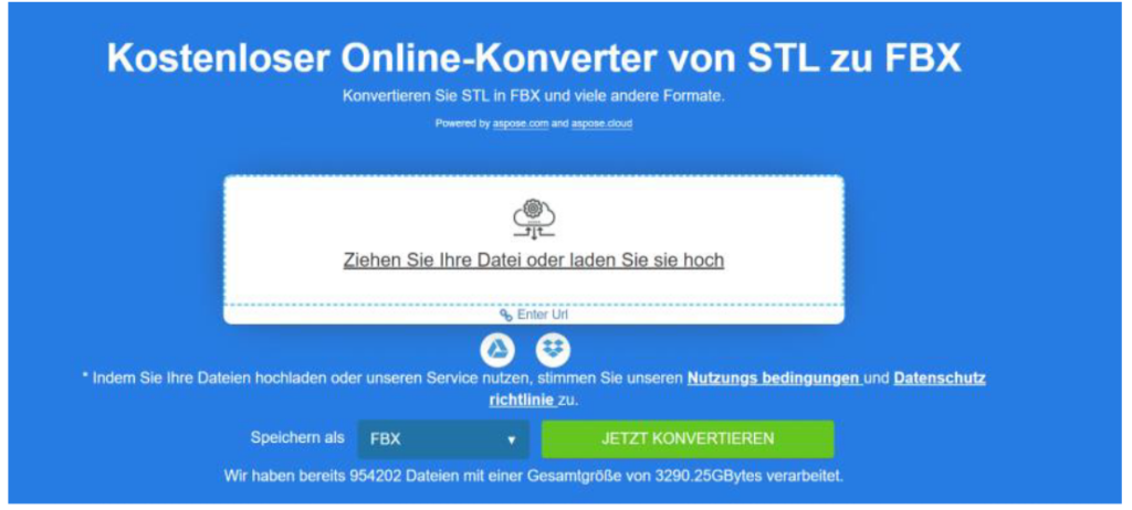
If you save it as an STL-file, you can convert it with the help of a converting program for free from the internet, into a FBX-file. This FBX-file you can import into Unity. The problem of this method is that you can only move the whole module and not individual parts.
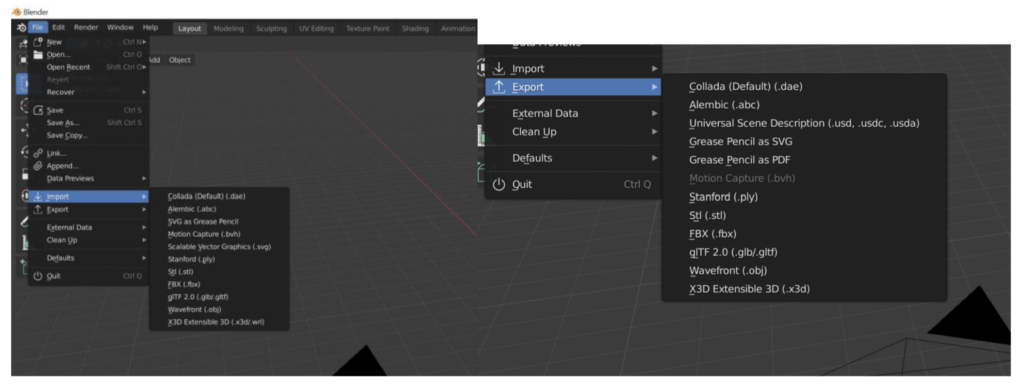
2. Next you have to import the VRML-file in Blender.
3. The FBX-file can be imported in Unity and now you can operate the individual parts of the CAD machine.
Vilnius College of Technologies and Design – Lithuania
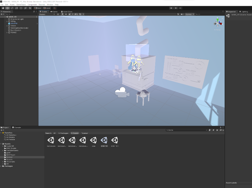
VR project was created using VR template in unity
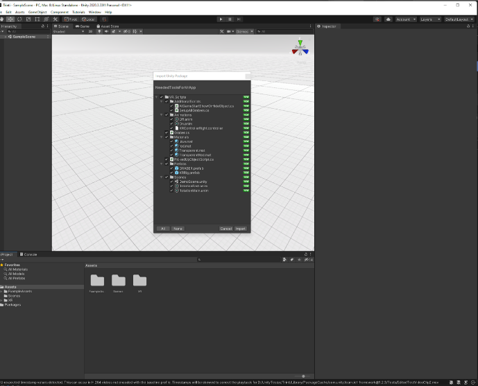
Imported Needed Tools For VR A nitypackage.
NeededToolsForVrApp.
Unity package has prepared basic scripts for application.
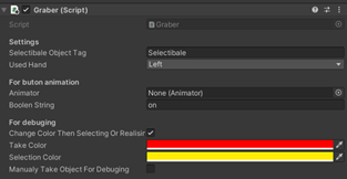
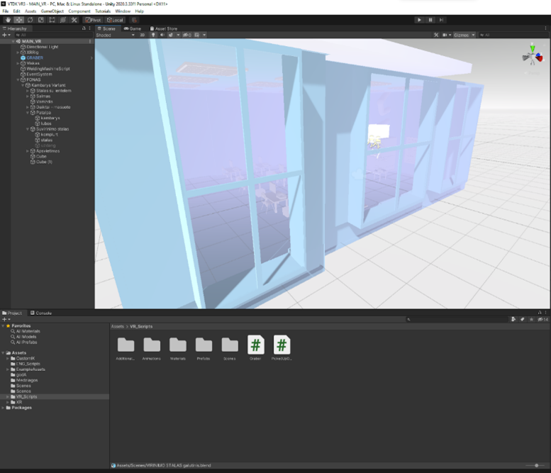
Prefab GRABER has to be attached (made child) to the controller and chosen hand (left or right).
Script PickedUpObjectScript.cs has to be attached to the object which you want to pick up.
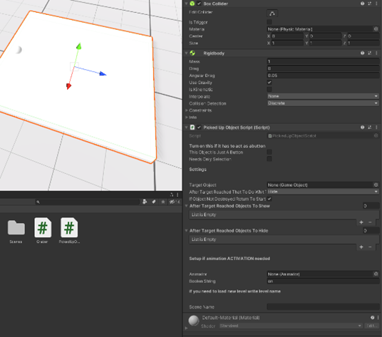
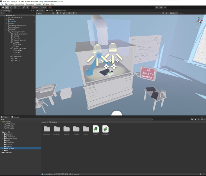
Game logic can be made using this script. Needed objects can be hidden or shown.
Result (models was prepared / created with blender program)
Results
Videos
Working package to repeat the process
• A method was developed to create such products.
• All steps are simplified to avoid programming, but complex situations can be put together.
Rzeszow University of Technology (PRz) – Poland
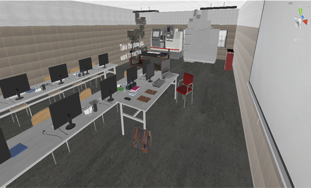
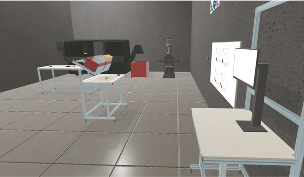
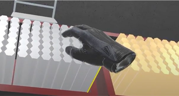
The process of machining in virtual reality is performed as follows. After launching the application, the user is taken to a room with a table, a raw material, tools and a CNC machine. Each step required for the user to progress is highlighted. The first task is to attach the tool to the handle. The user is required to grab the right tool and put it in the corresponding handle. If the step was performed correctly the pieces will be fused together. The next step is to place the handle with the tool in the chamber of the CNC machine. The operator needs to grab the handle and place it in the highlighted area of the machine (tool feeder). After placing the tool in the chamber, it is required to add the raw material. It’s an unworked shaft placed on the table. The user is required to grab it and place it in the appropriate mount in CNC machine (fig. 1).
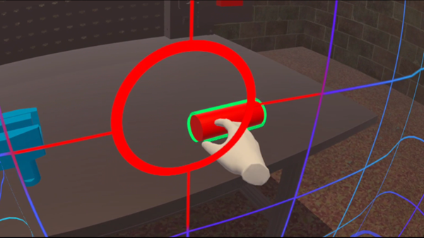
Figure 1. A raw material
Once the step is completed, the door, which must be manually closed, will light up. If the door was closed correctly, an animation of the first part of the process will start. With this the first stage of the training is complete. The second stage is machining the other side of raw material. Operator needs to open the door of the CNC machine and place another tool in the second slot of the tool feeder. Similarly, to before the tool and the handle need to be connected and placed it in the chamber. When the user has completed the process, the door outline will light up, allowing it to be closed. After the door is closed the second animation showing the rest of the machining process, will play (fig. 2).
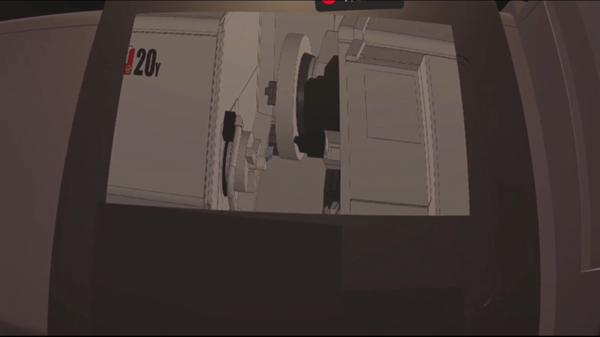
Figure 2. Second animation
When the animation finishes, the door can be opened. The operator can take out the finished part and view it up close (fig. 3).
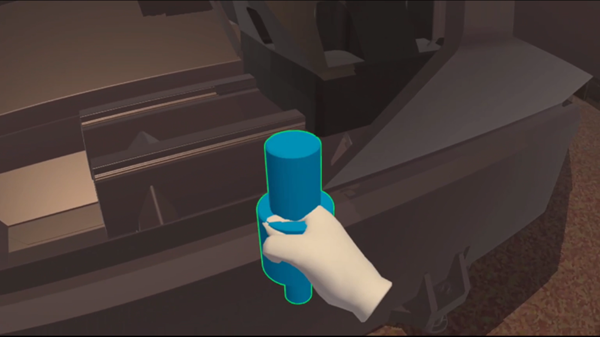
Figure 3. Finished material
Removal of the completed piece ends the training scenario. The user can restart the scenario by pressing the reset button located above the table.
IES MOLÍ DEL SOL – Spain
- Definition of the part to be manufactured
- Study of the machines to be used
- Written elaboration of the sequence to have all the steps
- Define the interactions that are needed
- Draw the classroom in CAD
- Translate this file to .obj and .fbx
- Creation of videos from the sequence
- Search for standard objects (chairs, tables, machines, etc.) in libraries
- Search for training videos in Unity
Technical School Osijek – Croatia
To make our program, we first downloaded Unity Hub and installed all the required plugins. To be able to launch our project in our VR headset, we had to install the Android SDK. Next, we had to install the XR interaction toolkit, enable Quest 2 in the platform, and then also switch platform to Android in build settings.
After we have set up Unity to support our VR headset, we started working on the VR camera and controllers. To do that, we have used the XR origin preset, which comes with the camera preset for the headset. Next, we have added the controllers and their models, along with the functions to grab things with the grab button and to move with the joysticks.
To make the classroom, we measured the classroom and designed it in 3DS CATIA V5. Then we used CAD exporter to import the catpart files to .obj files which we needed to be able to export them to Unity.
We had to add materials to the mesh, along with the rigidbody and collider components.
Some of our objects in the room are made in Unity or a modelling software by ourselves, but not all. Some of the models we have imported from websites like GrabCAD, SketchFab and other model libraries. Each object needed to have a material added to it. To add the possibility to grab and hold objects, we had to also add colliders and rigidbody, but also the XR Grab Interactable.
To make the machine, we had to make or import a model and write scripts to move the X, Y and Z axis. Since our model was downloaded, we also had to separate the doors from the main chassis of the machine in Blender. The scripts were written in the Microsoft Visual Studio software using the C# programming language.
Some of the things we still need to work on is animations for the machining process, functions that close and open the machine door along with the option to grab the door handle, player model collision and functions to turn the raw material into the finished product.